per·se·ver·ance (n)
Steadfastness in doing something despite difficulty or delay in achieving success.


In this post, I will discuss a little background on what Humidity is and how a DHT11 sensor measures Humidity. After that, I’ll show you how to connect the DHT11 to the Arduino and give you some example code so you can use the DHT11 in your own projects.


THE DHT11 SENSOR:


The DHT11 is a digital sensor that lets you easily get relative humidity and temperature readings in your projects. 


DHT11 Technical Specifications:
- Humidity Range: 20-90% RH
- Humidity Accuracy: ±5% RH
- Temperature Range: 0-50 °C
- Temperature Accuracy: ±2% °C
- Operating Voltage: 3V to 5.5V


WHAT IS RELATIVE HUMIDITY?


The DHT11 humidity and temperature sensor measures relative humidity (RH) and temperature. Relative humidity is the ratio of water vapor in air vs. the saturation point of water vapor in air. The saturation point of water vapor in air changes with temperature. Cold air can hold less water vapor before it is saturated, and hot air can hold more water vapor before it is saturated. The formula for relative humidity is as follows:
Relative Humidity = (density of water vapor / density of water vapor at saturation) x 100%
Basically, relative humidity is the amount of water in the air compared to the amount of water that air can hold before condensation occurs. It’s expressed as a percentage.  For example, at 100% RH condensation (or rain) occurs, and at 0% RH, the air is completely dry.


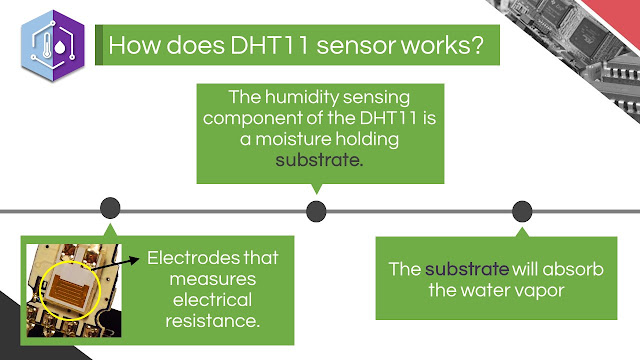
The DHT11 calculates relative humidity by measuring the electrical resistance between two electrodes. The humidity sensing component of the DHT11 is a moisture holding substrate (usually a salt or conductive plastic polymer) with the electrodes applied to the surface. When water vapor is absorbed by the substrate, ions are released by the substrate which increases the conductivity between the electrodes. The change in resistance between the two electrodes is proportional to the relative humidity. Higher relative humidity decreases the resistance between the electrodes while lower relative humidity increases the resistance between the electrodes.

The temperature readings from the DHT11 come from a surface mounted NTC temperature sensor (thermistor) built into the unit. To learn more about thermistors and how to use them on the Arduino, check out our Arduino Thermistor Temperature Sensor Tutorial.


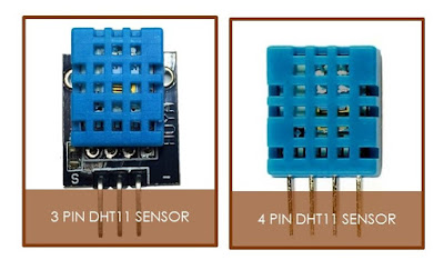
There are two different variations of the DHT11 sensor you might come across. One type has four pins, and the other type is mounted to a small PCB that has three pins. The PCB mounted version with three pins is nice since it includes a surface mounted 10K Ohm pull up resistor for the signal line:


1.Install the DHT Library:
Go to 'SKETCH' >> 'Include Library' >> 'Add Library' >> Select DHTLib.zip file.
NOTE: Restart the Arduino IDE in order for you to see the DHTLib in the installed list of library. 

2. Upload the sample program below to Arduino and open the serial monitor.

#include <dht.h>

dht DHT;

#define DHT11_PIN 7

void setup(){
  Serial.begin(9600);
}

void loop()
{
  int chk = DHT.read11(DHT11_PIN);
  Serial.print("Temperature = ");
  Serial.println(DHT.temperature);
  Serial.print("Humidity = ");
  Serial.println(DHT.humidity);
  delay(1000);
}


Files needed:
HumiditySensor.pdf
DHTLib.zip


Reference: http://www.electrical4u.com/universal-gate-nand-nor-gate-as-universal-gate/

UNIVERSAL GATE: NOR


We have discussed about NOR Gate on the previous article. Now coming to the topic of this article we are going to discuss about the Universal Gate. On the previous article, I discussed that NOR Gate is considered as UNIVERSAL GATE. Now NOR has the particular property that can create any logical Boolean expression if designed in a proper way. Now we will look at the operation of NOR gate as a universal gate.

As a review, this is the NOR Gate and its Truth table:

TRUTH TABLE:

 A B Y

0 0 1
0 1 0
1 0 0
1 1 0   


 I will now show you how to make a NOT Gate out of a NOR Gate:


universal nor gate 


TRUTH TABLE 

A Y
0 1
1 0


AND Gate derived from a NOR Gate:


universal nor gate 

 
TRUTH TABLE:

A B Y 
0 0 0
0 1 0
1 0 0
1 1 1  


Lastly, an OR Gate derived from a NOR Gate :


universal nand gate


TRUTH TABLE:

A B Y 
0 0 0
0 1 1
1 0 1
1 1 1  


That's it! You have now created a AND, NOT, and OR Gate out of a NOR Gate. Feel free to add questions on the comment section below.

Studying is really hard when your mind is clouded of stress, school projects, paper works, assignments, and etc. As a student, I also find it hard to study because of the distractions I have at home and at school. It is easier to grab your phone faster than to grab the nearest book beside you.Most students struggle whether to study or to spend their free time updating their social media apps. Below are studying hacks I've searched from the Internet that really helped me a lot in times of procrastination and laziness:


TURN OFF THE WIFI


If you really want to study or make an advance reading when you are at home, turning off the wifi of your device would really help you focus on what you are doing. I know it's hard, I've been through that before. Students from this generation are easily distracted because of the Internet. It is also advisable to block distracting sites on your computer (e.g Facebook, Twitter, Tumblr and etc.) for a set period of time.

Remedy: If turning off the wifi doesn't work, TURN OFF YOUR PHONE!!! Discipline yourself to wait until you've learned the lesson before you text someone or update your social media up.


TURN OFF YOUR COMPUTER/LAPTOP


Your computer unless you're really using it for school purposes is one of the things that can get you distracted from studying. When using your computer in studying it is important to note that the only page you have in your screen is the page you need to study. (eg. Power Point Presentation, Word documents, etc.)

Remedy: Just like your mobile device/tablet your computer should be turned off too if you're not using it in studying for the upcoming exam or when you're reading an advance lesson for your class. You need to close your facebook tab, email needs to go to avoid seeing notification emails from social media apps, games and chat sessions have to go. You will not be able to focus on studying with all the temptations of the web.


YOUR PHYSICAL NEEDS


Always remember that when your studying you are not against everyone.. YOU ARE AGAINST YOURSELF. Sometimes your physical needs and wants can be the biggest distraction you can have when studying. You can't prevent to get sleepy, get hungry or even go to the bathroom because you feel like peeing. All of these things can break your focus in studying.

Remedy: Anticipate your physical needs before you start studying. Use the bathroom. Snag some brain food and a beverage. Choose a time to study when you are the least tired. One thing that is common from the Internet that really helps the mind to focus is spraying an unfamiliar smell and chewing a gum that is unfamiliar also to your taste. FIGHT LAZINESS, that is one of the biggest enemy you'll encounter next to yourself.

YOUR FRIENDS


If you're planning to have a study partner or a group study, think again. Sometimes your friend/study partner can be the source of a lot of distraction when you are studying. Make sure that your study partner or your friend is really good in collaborative studying. Sometimes they can really keep you from studying, despite their best intentions.

Remedy : If your study partner/friends are not good when it comes to their study habits and they get easily distracted, it is advisable to study alone or you'll both end up distracted and unproductive for that day. If your friends truly care about you, then they will understand your need to learn! Real friends will give you space to study, and if they won't give it to you, you have to take it for the sake of your score.


SUCCESSFUL STUDY HABBIT


Aside from the listed things above there are still a wide scope of distractions you will encounter as you continue from studying. Below are some keys to consider in order for you to have a good and successful study habit:


- The key to a successful study habit is not attempting to cram all your studying into one session. Our mind has its limitations and it cannot absorb all the information we need in just one snap.


- Successful study habits also happen when you have a plan on when you're going to study.
You should set a specific goal every time you're studying.

- Never delay or procrastinate your planned study session. always remember that time is important and you can't go back to it as much as you want. It's better to act now than to have regrets because you didn't study for that moment.


That would be all! thank you for reading! :D


THE  NOR  GATE


   The Logic NOR Gate or Inclusive-NOR gate is a combination of the digital logic OR gate with that of an inverter or NOT gate connected together in series. The NOR (Not – OR) gate has an output that is normally at logic level “1” and only goes “LOW” to logic level “0” when ANY of its inputs are at logic level “1”. The Logic NOR Gate is the reverse or “Complementary” form of the OR gate.


Electronics symbol for NOR Gate


Truth Table


2-input NOR Gate

Symbol Truth Table
2-input nor gate
2-input NOR Gate
B A Q
0 0 1
0 1 0
1 0 0
1 1 0
Boolean Expression Q = A+B Read as A OR B gives NOT Q


3-input NOR Gate

Symbol Truth Table
3-input nor gate
3-input NOR Gate
C B A Q
0 0 0 1
0 0 1 0
0 1 0 0
0 1 1 0
1 0 0 0
1 0 1 0
1 1 0 0
1 1 1 0
Boolean Expression Q = A+B+C Read as A OR B OR C gives NOT Q


THE 7402 IC


          7402 IC is a device containing four independent gates each of which performs the logic NOR function. 

                           1. Output of the first NOR Gate
                           2. First input of the first NOR Gate
                           3. Second input of the first NOR Gate
                           4. Output of the second NOR Gate
                           5. First input of the second NOR Gate
                           6. Second input of the second NOR Gate
                           7. Ground/ Negative supply
                           8. First input of the third NOR Gate
                           9. Second input of the third NOR Gate 
                           10. Output of the third NOR Gate
                           11. First input of the fourth NOR Gate
                           12. Second input of the fourth NOR Gate
                           13. Output of the fourth NOR Gate
                           14.  VCC/Positive Supply 


DID YOU KNOW THAT WE CAN USE NOR GATE AS A UNIVERSAL LOGIC CIRCUIT? A NOR GATE CAN MAKE A NOT, OR, AND GATE AND ETC. FIND OUT HERE.


DISPLAYING CUSTOM CHARACTERS ON LCD USING PIC16F877A 


Reference: https://electrosome.com/custom-characters-lcd-pic-mikroc/

NOTE: Please go through the tutorial on Interfacing Character LCD with PIC Microcontroller – MicroC Pro.


     Let us first discuss some of the basic concepts and terminologies that we are going to use in displaying custom characters on our 16x2 LCD. Basically, the LCD is consist of 3 memory blocks called CGROMDDRAM, and CGRAM.


Character Generation ROM (CGROM)
       This is the memory which holds the 5×8 or the 5×10 dot patterns of predefined characters in the LCD. It can create 208 5x8 character dot patterns and 32 5x10 character dot patterns.


Display Data RAM (DDRAM)
        Just like our personal computers, the LCD also has a RAM and it is called DDRAM. This is the memory which holds the character data which is currently displayed on the LCD. Its capacity is 80x8 bits.

Character Generation RAM (CGRAM)
        This memory works similar to CGROM as this is a RAM we can modify its data anytime. We can store our custom character patterns in this memory through program. We can store up to eight 5x8 character dot patterns and four 5x10 character dot patterns in this memory.

The starting address of the CGRAM is from 00-07.


Creating your own Custom Characters


  1. On your Microsoft Excel software create a 5x8 box just like the picture above. That will serve as our 5x8 dot pattern as seen on our LCD. 
  2. To create your custom character, just fill the box that will satisfy your design.
  3. The shaded boxes are labeled 1 and the unshaded boxes are labeled as 0. Since we are processing 8 bits of data, the first column of boxes serves as our higher bit data and the remaining column of boxes is our lower bit data.
  4. On our example above, just convert the binary form of data into decimal.

MODIFIED CODE:


// LCD module connections
sbit LCD_RS at RD2_bit;
sbit LCD_EN at RD3_bit;
sbit LCD_D4 at RD4_bit;
sbit LCD_D5 at RD5_bit;
sbit LCD_D6 at RD6_bit;
sbit LCD_D7 at RD7_bit;

sbit LCD_RS_Direction at TRISD2_bit;
sbit LCD_EN_Direction at TRISD3_bit;
sbit LCD_D4_Direction at TRISD4_bit;
sbit LCD_D5_Direction at TRISD5_bit;
sbit LCD_D6_Direction at TRISD6_bit;
sbit LCD_D7_Direction at TRISD7_bit;
// End LCD module connections

const char character0[] = {0,0,10,31,31,14,4,0};
const char character1[] = {14,27,17,17,17,17,31,0};
const char character2[] = {14,27,17,17,17,31,31,0};
const char character3[] = {14,27,17,17,31,31,31,0};
const char character4[] = {14,27,17,31,31,31,31,0};
const char character5[] = {14,31,31,31,31,31,31,0};
const char character6[] = {0,4,2,31,2,4,0,0};
const char character7[] = {0,0,14,17,17,10,27,0};

void CustomChar0() {
  char i;
  Lcd_Cmd(64);
  for (i = 0; i<=7; i++) Lcd_Chr_CP(character0[i]);
  Lcd_Cmd(_LCD_RETURN_HOME);
}

void CustomChar1() {
  char i;
  Lcd_Cmd(72);
  for (i = 0; i<=7; i++) Lcd_Chr_CP(character1[i]);
  Lcd_Cmd(_LCD_RETURN_HOME);
}

void CustomChar2() {
  char i;
  Lcd_Cmd(80);
  for (i = 0; i<=7; i++) Lcd_Chr_CP(character2[i]);
  Lcd_Cmd(_LCD_RETURN_HOME);
}

void CustomChar3() {
  char i;
  Lcd_Cmd(88);
  for (i = 0; i<=7; i++) Lcd_Chr_CP(character3[i]);
  Lcd_Cmd(_LCD_RETURN_HOME);
}

void CustomChar4() {
  char i;
  Lcd_Cmd(96);
  for (i = 0; i<=7; i++) Lcd_Chr_CP(character4[i]);
  Lcd_Cmd(_LCD_RETURN_HOME);
}

void CustomChar5() {
  char i;
  Lcd_Cmd(104);
  for (i = 0; i<=7; i++) Lcd_Chr_CP(character5[i]);
  Lcd_Cmd(_LCD_RETURN_HOME);
}

void CustomChar6() {
  char i;
  Lcd_Cmd(112);
  for (i = 0; i<=7; i++) Lcd_Chr_CP(character6[i]);
  Lcd_Cmd(_LCD_RETURN_HOME);
}

void CustomChar7() {
  char i;
  Lcd_Cmd(120);
  for (i = 0; i<=7; i++) Lcd_Chr_CP(character7[i]);
  Lcd_Cmd(_LCD_RETURN_HOME);
}

void main()  {
  Lcd_Init(); // Initialize LCD

  Lcd_Cmd(_LCD_CLEAR); // Clear display
  Lcd_Cmd(_LCD_CURSOR_OFF); // Cursor off

  //Send Custom Charactors to CGRAM
  CustomChar0();
  CustomChar1();
  CustomChar2();
  CustomChar3();
  CustomChar4();
  CustomChar5();
  CustomChar6();
  CustomChar7();
  //End

  //Display Custom Characters
  Lcd_Chr(1,1,0);
  Delay_ms(1000);
  Lcd_Chr(1,2,1);
  Delay_ms(1000);
  Lcd_Chr(1,3,2);
  Delay_ms(1000);
  Lcd_Chr(1,4,3);
  Delay_ms(1000);
  Lcd_Chr(1,5,4);
  Delay_ms(1000);
  Lcd_Chr(1,6,5);
  Delay_ms(1000);
  Lcd_Chr(1,7,6);
  Delay_ms(1000);
  Lcd_Chr(1,8,7);
  Delay_ms(1000);
}
NOTE: Some of the syntax of the code might not build on your project because of the version of MikroC programmer you are using. Just go to the Help and go to the LCD Library of your MikroC programmer to check the right syntax of your program. It is also nice to drop some of your questions on the comment section below.


author
John Aldrin T. Mantes
Hi! Welcome to my Blog. This blog is part of our requirement in our Educational Technology class. The content of the blog is comprise of the discussions during the Observation and Participation class. Feel free to ask questions on the comment section. Have a great Day.